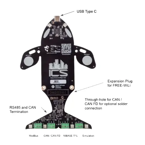
Whale Tail Badge Tour and Pinout
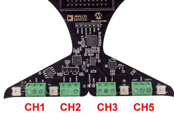
Pinout

| PIN# | 1 | 2 | 3 |
|---|---|---|---|
| CH1 - ModBus | A | GND | B |
| CH2 - CAN FD | CAN L | GND | CAN H |
| CH3 - 10BASE-T1L | T1L- | GND | T1L+ |
| CH4 - Sensor Simulator | Loop | GND | Loop + |
GPIO Pin Descriptions
The table below describes the pins. All GPIO except dedicated pins can be used bidirectionally depending on the application. So the directions are the default.
| Pin | Description | Default Direction | Notes |
|---|---|---|---|
| 1 | |||
| 2 | 5V Out | Output | 5V to power IO and external circuit |
| 3 | GPIO27 OUT | Output | RPi 2040 GPIO27 |
| 4 | V PINS IN | Input | Input to set the IO voltage 1.1 to 5.5V |
| 5 | UART1 Rx IN | Input | RPi 2040 UART 1 Receive (GPIO9) |
| 6 | 3.3V Out | Output | 3.3 V to Power IO and external circuit |
| 7 | UART1 CTS IN | Input | RPi 2040 UART 1 Clear To Send (GPIO10)5 |
| 8 | |||
| 9 | UART1 TX OUT | Output | RPi 2040 UART1 Transmit (GPIO8) |
| 10 | |||
| 11 | UART1 RTS OUT | Output | RPi 2040 UART 1 Request To Send (GPIO11) |
| 12 | |||
| 13 | |||
| 14 | GPIO 26 IN | Input | RPi 2040 GPIO26 |
| 15 | SPI1 SCLK OUT | Output | RPi 2040 SPI 1 Clock (GPIO14) |
| 16 | |||
| 17 | GPIO25 OUT | Output | RPi 2040 GPIO25. GPIO25 also connects to board status LED (same as RPi Pico) |
| 18 | |||
| 19 | GND | ||
| 20 | GND |
